In this modern era, organizations greatly rely on computer networks to share information throughout the organization in an efficient and productive manner. Organizational computer networks are now becoming large and ubiquitous. Assuming that each staff member has a dedicated workstation, a large scale company would have few thousands workstations and many server on the network.
It is likely that these workstations may not be centrally managed, nor would they have perimeter protection. They may have a variety of operating systems, hardware, software, and protocols, with different level of cyber awareness among users. Now imagine, these thousands of workstations on company network are directly connected to the Internet. This sort of unsecured network becomes a target for an attack which holds valuable information and displays vulnerabilities.
In this chapter, we describe the major vulnerabilities of the network and significance of network security. In subsequent chapters, we will discuss the methods to achieve the same.
Physical Network
A network is defined as two or more computing devices connected together for sharing resources efficiently. Further, connecting two or more networks together is known as internetworking. Thus, the Internet is just an internetwork – a collection of interconnected networks.
For setting up its internal network, an organization has various options. It can use a wired network or a wireless network to connect all workstations. Nowadays, organizations are mostly using a combination of both wired and wireless networks.
Wired & Wireless Networks
In a wired network, devices are connected to each other using cables. Typically, wired networks are based on Ethernet protocol where devices are connected using the Unshielded Twisted Pair (UTP) cables to the different switches. These switches are further connected to the network router for accessing the Internet.
In wireless network, the device is connected to an access point through radio transmissions. The access points are further connected through cables to switch/router for external network access.
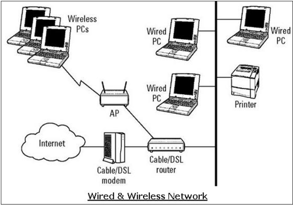
Wireless networks have gained popularity due to the mobility offered by them. Mobile devices need not be tied to a cable and can roam freely within the wireless network range. This ensures efficient information sharing and boosts productivity.
Vulnerabilities & Attacks
The common vulnerability that exists in both wired and wireless networks is an “unauthorized access” to a network. An attacker can connect his device to a network though unsecure hub/switch port. In this regard, wireless network are considered less secure than wired network, because wireless network can be easily accessed without any physical connection.
After accessing, an attacker can exploit this vulnerability to launch attacks such as −
- Sniffing the packet data to steal valuable information.
- Denial of service to legitimate users on a network by flooding the network medium with spurious packets.
- Spoofing physical identities (MAC) of legitimate hosts and then stealing data or further launching a ‘man-in-the-middle’ attack.
Network Protocol
Network Protocol is a set of rules that govern communications between devices connected on a network. They include mechanisms for making connections, as well as formatting rules for data packaging for messages sent and received.
Several computer network protocols have been developed each designed for specific purposes. The popular and widely used protocols are TCP/IP with associated higher- and lower-level protocols.
TCP/IP Protocol
Transmission Control Protocol (TCP) and Internet Protocol (IP) are two distinct computer network protocols mostly used together. Due to their popularity and wide adoption, they are built in all operating systems of networked devices.
IP corresponds to the Network layer (Layer 3) whereas TCP corresponds to the Transport layer (Layer 4) in OSI. TCP/IP applies to network communications where the TCP transport is used to deliver data across IP networks.
TCP/IP protocols are commonly used with other protocols such as HTTP, FTP, SSH at application layer and Ethernet at the data link/physical layer.
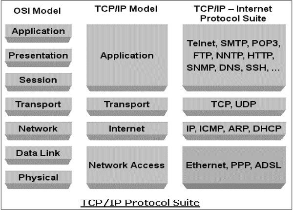
TCP/IP protocol suite was created in 1980 as an internetworking solution with very little concern for security aspects.
It was developed for a communication in the limited trusted network. However, over a period, this protocol became the de-facto standard for the unsecured Internet communication.
Some of the common security vulnerabilities of TCP/IP protocol suits are −
- HTTP is an application layer protocol in TCP/IP suite used for transfer files that make up the web pages from the web servers. These transfers are done in plain text and an intruder can easily read the data packets exchanged between the server and a client.
- Another HTTP vulnerability is a weak authentication between the client and the web server during the initializing of the session. This vulnerability can lead to a session hijacking attack where the attacker steals an HTTP session of the legitimate user.
- TCP protocol vulnerability is three-way handshake for connection establishment. An attacker can launch a denial of service attack “SYN-flooding” to exploit this vulnerability. He establishes lot of half-opened sessions by not completing handshake. This leads to server overloading and eventually a crash.
- IP layer is susceptible to many vulnerabilities. Through an IP protocol header modification, an attacker can launch an IP spoofing attack.
Apart from the above-mentioned, many other security vulnerabilities exist in the TCP/IP Protocol family in design as well in its implementation.
Incidentally, in TCP/IP based network communication, if one layer is hacked, the other layers do not become aware of the hack and the entire communication gets compromised. Hence, there is need to employ security controls at each layer to ensure foolproof security.
DNS Protocol
Domain Name System (DNS) is used to resolve host domain names to IP addresses. Network users depend on DNS functionality mainly during browsing the Internet by typing a URL in the web browser.
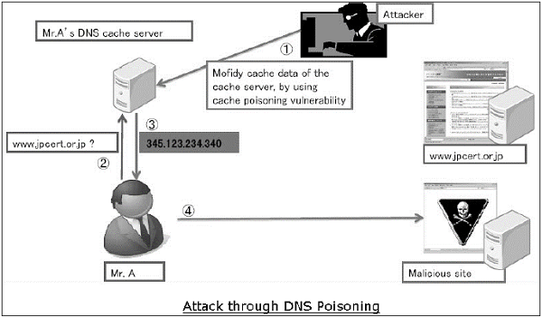
In an attack on DNS, an attacker’s aim is to modify a legitimate DNS record so that it gets resolved to an incorrect IP address. It can direct all traffic for that IP to the wrong computer. An attacker can either exploit DNS protocol vulnerability or compromise the DNS server for materializing an attack.
DNS cache poisoning is an attack exploiting a vulnerability found in the DNS protocol. An attacker may poison the cache by forging a response to a recursive DNS query sent by a resolver to an authoritative server. Once, the cache of DNS resolver is poisoned, the host will get directed to a malicious website and may compromise credential information by communication to this site.
ICMP Protocol
Internet Control Management Protocol (ICMP) is a basic network management protocol of the TCP/IP networks. It is used to send error and control messages regarding the status of networked devices.
ICMP is an integral part of the IP network implementation and thus is present in very network setup. ICMP has its own vulnerabilities and can be abused to launch an attack on a network.
The common attacks that can occur on a network due to ICMP vulnerabilities are −
- ICMP allows an attacker to carry out network reconnaissance to determine network topology and paths into the network. ICMP sweep involves discovering all host IP addresses which are alive in the entire target’s network.
- Trace route is a popular ICMP utility that is used to map target networking by describing the path in real-time from the client to the remote host.
- An attacker can launch a denial of service attack using the ICMP vulnerability. This attack involves sending IPMP ping packets that exceeds 65,535 bytes to the target device. The target computer fails to handle this packet properly and can cause the operating system to crush.
Other protocols such as ARP, DHCP, SMTP, etc. also have their vulnerabilities that can be exploited by the attacker to compromise the network security. We will discuss some of these vulnerabilities in later chapters.
The least concern for the security aspect during design and implementation of protocols has turned into a main cause of threats to the network security.
Goals of Network Security
As discussed in earlier sections, there exists large number of vulnerabilities in the network. Thus, during transmission, data is highly vulnerable to attacks. An attacker can target the communication channel, obtain the data, and read the same or re-insert a false message to achieve his nefarious aims.
Network security is not only concerned about the security of the computers at each end of the communication chain; however, it aims to ensure that the entire network is secure.
Network security entails protecting the usability, reliability, integrity, and safety of network and data. Effective network security defeats a variety of threats from entering or spreading on a network.
The primary goal of network security are Confidentiality, Integrity, and Availability. These three pillars of Network Security are often represented as CIA triangle.
- Confidentiality − The function of confidentiality is to protect precious business data from unauthorized persons. Confidentiality part of network security makes sure that the data is available only to the intended and authorized persons.
- Integrity − This goal means maintaining and assuring the accuracy and consistency of data. The function of integrity is to make sure that the data is reliable and is not changed by unauthorized persons.
- Availability − The function of availability in Network Security is to make sure that the data, network resources/services are continuously available to the legitimate users, whenever they require it.
Achieving Network Security
Ensuring network security may appear to be very simple. The goals to be achieved seems to be straightforward. But in reality, the mechanisms used to achieve these goals are highly complex, and understanding them involves sound reasoning.
International Telecommunication Union (ITU), in its recommendation on security architecture X.800, has defined certain mechanisms to bring the standardization in methods to achieve network security. Some of these mechanisms are −
- En-cipherment − This mechanism provides data confidentiality services by transforming data into not-readable forms for the unauthorized persons. This mechanism uses encryption-decryption algorithm with secret keys.
- Digital signatures − This mechanism is the electronic equivalent of ordinary signatures in electronic data. It provides authenticity of the data.
- Access control − This mechanism is used to provide access control services. These mechanisms may use the identification and authentication of an entity to determine and enforce the access rights of the entity.
Having developed and identified various security mechanisms for achieving network security, it is essential to decide where to apply them; both physically (at what location) and logically (at what layer of an architecture such as TCP/IP).
Security Mechanisms at Networking Layers
Several security mechanisms have been developed in such a way that they can be developed at a specific layer of the OSI network layer model.
- Security at Application Layer − Security measures used at this layer are application specific. Different types of application would need separate security measures. In order to ensure application layer security, the applications need to be modified.It is considered that designing a cryptographically sound application protocol is very difficult and implementing it properly is even more challenging. Hence, application layer security mechanisms for protecting network communications are preferred to be only standards-based solutions that have been in use for some time.An example of application layer security protocol is Secure Multipurpose Internet Mail Extensions (S/MIME), which is commonly used to encrypt e-mail messages. DNSSEC is another protocol at this layer used for secure exchange of DNS query messages.
- Security at Transport Layer − Security measures at this layer can be used to protect the data in a single communication session between two hosts. The most common use for transport layer security protocols is protecting the HTTP and FTP session traffic. The Transport Layer Security (TLS) and Secure Socket Layer (SSL) are the most common protocols used for this purpose.
- Network Layer − Security measures at this layer can be applied to all applications; thus, they are not application-specific. All network communications between two hosts or networks can be protected at this layer without modifying any application. In some environments, network layer security protocol such as Internet Protocol Security (IPsec) provides a much better solution than transport or application layer controls because of the difficulties in adding controls to individual applications. However, security protocols at this layer provides less communication flexibility that may be required by some applications.
Incidentally, a security mechanism designed to operate at a higher layer cannot provide protection for data at lower layers, because the lower layers perform functions of which the higher layers are not aware. Hence, it may be necessary to deploy multiple security mechanisms for enhancing the network security.
In the following chapters of the tutorial, we will discuss the security mechanisms employed at different layers of OSI networking architecture for achieving network security.
Network Security – Application Layer
Various business services are now offered online though client-server applications. The most popular forms are web application and e-mail. In both applications, the client communicates to the designated server and obtains services.
While using a service from any server application, the client and server exchange a lot of information on the underlying intranet or Internet. We are aware of fact that these information transactions are vulnerable to various attacks.
Network security entails securing data against attacks while it is in transit on a network. To achieve this goal, many real-time security protocols have been designed. Such protocol needs to provide at least the following primary objectives −
- The parties can negotiate interactively to authenticate each other.
- Establish a secret session key before exchanging information on network.
- Exchange the information in encrypted form.
Interestingly, these protocols work at different layers of networking model. For example, S/MIME protocol works at Application layer, SSL protocol is developed to work at transport layer, and IPsec protocol works at Network layer.

In this chapter, we will discuss different processes for achieving security for e-mail communication and associated security protocols. The method for securing DNS is covered subsequently. In the later chapters, the protocols to achieve web security will be described.
E-mail Security
Nowadays, e-mail has become very widely used network application. Let’s briefly discuss the e-mail infrastructure before proceeding to know about e-mail security protocols.
E-mail Infrastructure
The simplest way of sending an e-mail would be sending a message directly from the sender’s machine to the recipient’s machine. In this case, it is essential for both the machines to be running on the network simultaneously. However, this setup is impractical as users may occasionally connect their machines to the network.
Hence, the concept of setting up e-mail servers arrived. In this setup, the mail is sent to a mail server which is permanently available on the network. When the recipient’s machine connects to the network, it reads the mail from the mail server.
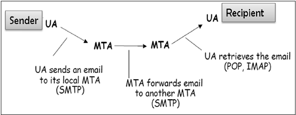
In general, the e-mail infrastructure consists of a mesh of mail servers, also termed as Message Transfer Agents (MTAs) and client machines running an e-mail program comprising of User Agent (UA) and local MTA.
Typically, an e-mail message gets forwarded from its UA, goes through the mesh of MTAs and finally reaches the UA on the recipient’s machine.

The protocols used for e-mail are as follows −
- Simple mail Transfer Protocol (SMTP) used for forwarding e-mail messages.
- Post Office Protocol (POP) and Internet Message Access Protocol (IMAP) are used to retrieve the messages by recipient from the server.
MIME
Basic Internet e-mail standard was written in 1982 and it describes the format of e-mail message exchanged on the Internet. It mainly supports e-mail message written as text in basic Roman alphabet.
By 1992, the need was felt to improve the same. Hence, an additional standard Multipurpose Internet Mail Extensions (MIME) was defined. It is a set of extensions to the basic Internet E-mail standard. MIME provides an ability to send e-mail using characters other than those of the basic Roman alphabet such as Cyrillic alphabet (used in Russian), the Greek alphabet, or even the ideographic characters of Chinese.
Another need fulfilled by MIME is to send non-text contents, such as images or video clips. Due to this features, the MIME standard became widely adopted with SMTP for e-mail communication.
E-Mail Security Services
Growing use of e-mail communication for important and crucial transactions demands provision of certain fundamental security services as the following −
- Confidentiality − E-mail message should not be read by anyone but the intended recipient.
- Authentication − E-mail recipient can be sure of the identity of the sender.
- Integrity − Assurance to the recipient that the e-mail message has not been altered since it was transmitted by the sender.
- Non-repudiation − E-mail recipient is able to prove to a third party that the sender really did send the message.
- Proof of submission − E-mail sender gets the confirmation that the message is handed to the mail delivery system.
- Proof of delivery − Sender gets a confirmation that the recipient received the message.
Security services such as privacy, authentication, message integrity, and non-repudiation are usually provided by using public key cryptography.
Typically, there are three different scenarios of e-mail communication. We will discuss the methods of achieving above security services in these scenarios.
One-to-One E-mail
In this scenario, the sender sends an e-mail message to only one recipient. Usually, not more than two MTA are involved in the communication.
Let’s assume a sender wants to send a confidential e-mail to a recipient. The provision of privacy in this case is achieved as follows −
- The sender and receiver have their private-public keys as (SPVT, SPUB) and (RPVT, RPUB) respectively.
- The sender generates a secret symmetric key, KS for encryption. Though the sender could have used RPUB for encryption, a symmetric key is used to achieve faster encryption and decryption.
- The sender encrypts message with key KS and also encrypts KS with public key of the recipient, RPUB.
- The sender sends encrypted message and encrypted KS to the recipient.
- The recipient first obtains KS by decrypting encoded KS using his private key, RPVT.
- The recipient then decrypts message using the symmetric key, KS.

If message integrity, authentication, and non-repudiation services are also needed in this scenario, the following steps are added to the above process.
- The sender produces hash of message and digitally signs this hash with his private key, SPVT.
- The sender sends this signed hash to the recipient along with other components.

- The recipient uses public key SPUB and extracts the hash received under the sender’s signature.
- The recipient then hashes the decrypted message and now compares the two hash values. If they match, message integrity is considered to be achieved.
- Also, the recipient is sure that the message is sent by the sender (authentication). And lastly, the sender cannot deny that he did not send the message (non-repudiation).
One-to-Multiple Recipients E-mail
In this scenario, the sender sends an e-mail message to two or more recipients. The list is managed by the sender’s e-mail program (UA + local MTA). All recipients get the same message.

Let’s assume, the sender wants to send confidential e-mail to many recipients (say R1, R2, and R3). The provision of privacy in this case is achieved as follows −
- The sender and all recipients have their own pair of private-public keys.
- The sender generates a secret symmetric key, Ks and encrypts the message with this key.
- The sender then encrypts KS multiple times with public keys of R1, R2, and R3, getting R1PUB(KS), R2PUB(KS), and R3PUB(KS).
- The sender sends encrypted message and corresponding encrypted KSto the recipient. For example, recipient 1 (R1) receives encrypted message and R1PUB(KS).
- Each recipient first extracts key KS by decrypting encoded KS using his private key.
- Each recipient then decrypts the message using the symmetric key, KS.
For providing the message integrity, authentication, and non-repudiation, the steps to be followed are similar to the steps mentioned above in one-to-one e-mail scenario.
One-to-Distribution List E-mail
In this scenario, the sender sends an e-mail message to two or more recipients but the list of recipients is not managed locally by the sender. Generally, the e-mail server (MTA) maintains the mailing list.
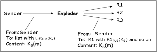
The sender sends a mail to the MTA managing the mailing list and then the mail is exploded by MTA to all recipients in the list.

In this case, when the sender wants to send a confidential e-mail to the recipients of the mailing list (say R1, R2, and R3); the privacy is ensured as follows −
- The sender and all recipients have their own pair of private-public keys. The Exploder Server has a pair of private-public key for each mailing list (ListPUB, ListPVT) maintained by it.
- The sender generates a secret symmetric key Ks and then encrypts the message with this key.
- The sender then encrypts KS with the public key associated with the list, obtains ListPUB(KS).
- The sender sends encrypted message and ListPUB(KS). The exploder MTA decrypts ListPUB(KS) using ListPVT and obtains KS.
- The exploder encrypts KS with as many public keys as there are members in the list.
- The Exploder forwards the received encrypted message and corresponding encrypted KS to all recipients in the list. For example, the Exploder forwards the encrypted message and R1PUB(KS) to recipient 1 and so on.
For providing the message integrity, authentication, and non-repudiation the steps to be followed are similar as given in case of one-to-one e-mail scenario.
Interestingly, the e-mail program employing above security method for securing e-mail is expected to work for all the possible scenarios discussed above. Most of the above security mechanisms for e-mail are provided by two popular schemes, Pretty Good Privacy (PGP) and S/MIME. We discuss both in the following sections.
PGP
Pretty Good Privacy (PGP) is an e-mail encryption scheme. It has become the de-facto standard for providing security services for e-mail communication.
As discussed above, it uses public key cryptography, symmetric key cryptography, hash function, and digital signature. It provides −
- Privacy
- Sender Authentication
- Message Integrity
- Non-repudiation
Along with these security services, it also provides data compression and key management support. PGP uses existing cryptographic algorithms such as RSA, IDEA, MD5, etc., rather than inventing the new ones.
Working of PGP

- Hash of the message is calculated. (MD5 algorithm)
- Resultant 128 bit hash is signed using the private key of the sender (RSA Algorithm).
- The digital signature is concatenated to message, and the result is compressed.
- A 128-bit symmetric key, KS is generated and used to encrypt the compressed message with IDEA.
- KS is encrypted using the public key of the recipient using RSA algorithm and the result is appended to the encrypted message.
The format of PGP message is shown in the following diagram. The IDs indicate which key is used to encrypt KS and which key is to be used to verify the signature on the hash.
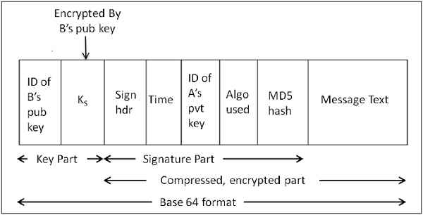
In PGP scheme, a message in signed and encrypted, and then MIME is encoded before transmission.
PGP Certificate
PGP key certificate is normally established through a chain of trust. For example, A’s public key is signed by B using his public key and B’s public key is signed by C using his public key. As this process goes on, it establishes a web of trust.
In a PGP environment, any user can act as a certifying authority. Any PGP user can certify another PGP user's public key. However, such a certificate is only valid to another user if the user recognizes the certifier as a trusted introducer.
Several issues exist with such a certification method. It may be difficult to find a chain leading from a known and trusted public key to desired key. Also, there might be multiple chains which can lead to different keys for desired user.
PGP can also use the PKI infrastructure with certification authority and public keys can be certified by CA (X.509 certificate).
S / MIME
S/MIME stands for Secure Multipurpose Internet Mail Extension. S/MIME is a secure e-mail standard. It is based on an earlier non-secure e-mailing standard called MIME.
Working of S/MIME
S/MIME approach is similar to PGP. It also uses public key cryptography, symmetric key cryptography, hash functions, and digital signatures. It provides similar security services as PGP for e-mail communication.
The most common symmetric ciphers used in S/MIME are RC2 and TripleDES. The usual public key method is RSA, and the hashing algorithm is SHA-1 or MD5.
S/MIME specifies the additional MIME type, such as “application/pkcs7-mime”, for data enveloping after encrypting. The whole MIME entity is encrypted and packed into an object. S/MIME has standardized cryptographic message formats (different from PGP). In fact, MIME is extended with some keywords to identify the encrypted and/or signed parts in the message.
S/MIME relies on X.509 certificates for public key distribution. It needs top-down hierarchical PKI for certification support.
Employability of S/MIME
Due to the requirement of a certificate from certification authority for implementation, not all users can take advantage of S/MIME, as some may wish to encrypt a message, with a public/private key pair. For example, without the involvement or administrative overhead of certificates.
In practice, although most e-mailing applications implement S/MIME, the certificate enrollment process is complex. Instead PGP support usually requires adding a plug-in and that plug-in comes with all that is needed to manage keys. The Web of Trust is not really used. People exchange their public keys over another medium. Once obtained, they keep a copy of public keys of those with whom e-mails are usually exchanged.
Implementation layer in network architecture for PGP and S/MIME schemes is shown in the following image. Both these schemes provide application level security of for e-mail communication.

One of the schemes, either PGP or S/MIME, is used depending on the environment. A secure e-email communication in a captive network can be provided by adapting to PGP. For e-mail security over Internet, where mails are exchanged with new unknown users very often, S/MIME is considered as a good option.
DNS Security
In the first chapter, we have mentioned that an attacker can use DNS Cache Poisoning to carry out an attack on the target user. Domain Name System Security Extensions (DNSSEC) is an Internet standard that can foil such attacks.
Vulnerability of Standard DNS
In a standard DNS scheme, whenever the user wants to connect to any domain name, his computer contacts the DNS server and looks up the associated IP address for that domain name. Once IP address is obtained, the computer then connects to that IP address.
In this scheme, there is no verification process involved at all. A computer asks its DNS server for the address associated with a website, the DNS server responds with an IP address, and your computer undoubtedly accepts it as legitimate response and connects to that website.
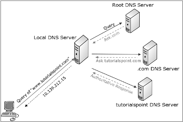
A DNS lookup actually happens in several stages. For example, when a computer asks for “www.tutorialspoint.com”, a DNS lookup is performed in several stages −
- The computer first asks the local DNS server (ISP provided). If ISP has this name in its cache, it responds else forwards the query to “root zone directory” where it can find “.com.” and root zone replies.
- Based on the reply, the computer then asks the “.com” directory where it can find “tutorialspoint.com.”
- Based on the information received, the computer inquires “tutorialspoint.com” where it can find www. tutorialspoint.com.
DNSSEC Defined
DNS lookup, when performed using DNSSEC, involves signing of replies by the responding entity. DNSSEC is based on public-key cryptography.
In DNSSEC standard, every DNS zone has a public/private key pair. All information sent by a DNS server is signed with the originating zone’s private key for ensuring authenticity. DNS clients need to know the zone’s public keys to check the signatures. Clients may be preconfigured with the public keys of all the top-level domains, or root DNS.
With DNSSEC, the lookup process goes as follows −
- When your computer goes to ask the root zone where it can find .com, the reply is signed by the root zone server.
- Computer checks the root zone’s signing key and confirms that it is the legitimate root zone with true information.
- In the reply, the root zone provides the information on the signing key of .com zone server and its location, allowing the computer to contact the .com directory and ensuring it is legitimate.
- The .com directory then provides the signing key and information for tutorialspoint.com, allowing it to contact google.com and verify that you are connected to the real tutorialspoint.com, as confirmed by the zones above it.
- The information sent is in the form of Resource Record Set (RRSets). The example of RRSet for domain “tutorialspoint.com” in top-level “.com” server is shown in the following table.
| Domain Name | Time to live | Type | Value |
|---|---|---|---|
| tutorialspoint.com | 86400 | NS | dns.tutorialspoint.com |
| dns.tutorialspoint.com | 86400 | A | 36..1.2.3 |
| tutorialspoint.com | 86400 | KEY | 3682793A7B73F731029CE2737D... |
| tutorialspoint.com | 86400 | SIG | 86947503A8B848F5272E53930C... |
- The KEY record is a public key of “tutorialspoint.com”.
- The SIG record is the top-level .com server's signed hash of the fields NS, A, and KEY records to verify their authenticity. Its value is Kcompvt(H(NS,A,KEY)).
Thus, it is considered that when DNSSEC is fully rolled out, the user’s computer is able to confirm that DNS responses are legitimate and true, and avoid DNS attacks launched through DNS cache poisoning.
Summary
The process of securing e-mails ensures the end-to-end security of the communication. It provides security services of confidentiality, sender authentication, message integrity, and non-repudiation.
Two schemes have been developed for e-mail security: PGP and S/MIME. Both these schemes use secret-key and public-key cryptography.
Standard DNS lookup is vulnerable to the attacks such as DNS spoofing/cache poisoning. Securing DNS lookup is feasible through the use of DNSSEC which employs the public-key cryptography.
In this chapter, we discussed the mechanisms used at application layer to provide network security for end-to-end communication.
Network Security – Transport Layer
Network security entails securing data against attacks while it is in transit on a network. To achieve this goal, many real-time security protocols have been designed. There are popular standards for real-time network security protocols such as S/MIME, SSL/TLS, SSH, and IPsec. As mentioned earlier, these protocols work at different layers of networking model.
In the last chapter, we discussed some popular protocols that are designed to provide application layer security. In this chapter, we will discuss the process of achieving network security at Transport Layer and associated security protocols.
For TCP/IP protocol based network, physical and data link layers are typically implemented in the user terminal and network card hardware. TCP and IP layers are implemented in the operating system. Anything above TCP/IP is implemented as user process.
Need for Transport Layer Security
Let's discuss a typical Internet-based business transaction.
Bob visits Alice’s website for selling goods. In a form on the website, Bob enters the type of good and quantity desired, his address and payment card details. Bob clicks on Submit and waits for delivery of goods with debit of price amount from his account. All this sounds good, but in absence of network security, Bob could be in for a few surprises.
- If transactions did not use confidentiality (encryption), an attacker could obtain his payment card information. The attacker can then make purchases at Bob's expense.
- If no data integrity measure is used, an attacker could modify Bob's order in terms of type or quantity of goods.
- Lastly, if no server authentication is used, a server could display Alice's famous logo but the site could be a malicious site maintained by an attacker, who is masquerading as Alice. After receiving Bob's order, he could take Bob's money and flee. Or he could carry out an identity theft by collecting Bob's name and credit card details.
Transport layer security schemes can address these problems by enhancing TCP/IP based network communication with confidentiality, data integrity, server authentication, and client authentication.
The security at this layer is mostly used to secure HTTP based web transactions on a network. However, it can be employed by any application running over TCP.
Philosophy of TLS Design
Transport Layer Security (TLS) protocols operate above the TCP layer. Design of these protocols use popular Application Program Interfaces (API) to TCP, called “sockets" for interfacing with TCP layer.
Applications are now interfaced to Transport Security Layer instead of TCP directly. Transport Security Layer provides a simple API with sockets, which is similar and analogous to TCP's API.
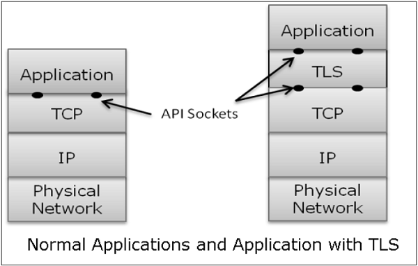
In the above diagram, although TLS technically resides between application and transport layer, from the common perspective it is a transport protocol that acts as TCP layer enhanced with security services.
TLS is designed to operate over TCP, the reliable layer 4 protocol (not on UDP protocol), to make design of TLS much simpler, because it doesn't have to worry about ‘timing out’ and ‘retransmitting lost data’. The TCP layer continues doing that as usual which serves the need of TLS.
Why TLS is Popular?
The reason for popularity of using a security at Transport Layer is simplicity. Design and deployment of security at this layer does not require any change in TCP/IP protocols that are implemented in an operating system. Only user processes and applications needs to be designed/modified which is less complex.
Secure Socket Layer (SSL)
In this section, we discuss the family of protocols designed for TLS. The family includes SSL versions 2 and 3 and TLS protocol. SSLv2 has been now replaced by SSLv3, so we will focus on SSL v3 and TLS.
Brief History of SSL
In year 1995, Netscape developed SSLv2 and used in Netscape Navigator 1.1. The SSL version1 was never published and used. Later, Microsoft improved upon SSLv2 and introduced another similar protocol named Private Communications Technology (PCT).
Netscape substantially improved SSLv2 on various security issues and deployed SSLv3 in 1999. The Internet Engineering Task Force (IETF) subsequently, introduced a similar TLS (Transport Layer Security) protocol as an open standard. TLS protocol is non-interoperable with SSLv3.
TLS modified the cryptographic algorithms for key expansion and authentication. Also, TLS suggested use of open crypto Diffie-Hellman (DH) and Digital Signature Standard (DSS) in place of patented RSA crypto used in SSL. But due to expiry of RSA patent in 2000, there existed no strong reasons for users to shift away from the widely deployed SSLv3 to TLS.
Salient Features of SSL
The salient features of SSL protocol are as follows −
- SSL provides network connection security through −
- Confidentiality − Information is exchanged in an encrypted form.
- Authentication − Communication entities identify each other through the use of digital certificates. Web-server authentication is mandatory whereas client authentication is kept optional.
- Reliability − Maintains message integrity checks.
- SSL is available for all TCP applications.
- Supported by almost all web browsers.
- Provides ease in doing business with new online entities.
- Developed primarily for Web e-commerce.
Architecture of SSL
SSL is specific to TCP and it does not work with UDP. SSL provides Application Programming Interface (API) to applications. C and Java SSL libraries/classes are readily available.
SSL protocol is designed to interwork between application and transport layer as shown in the following image −
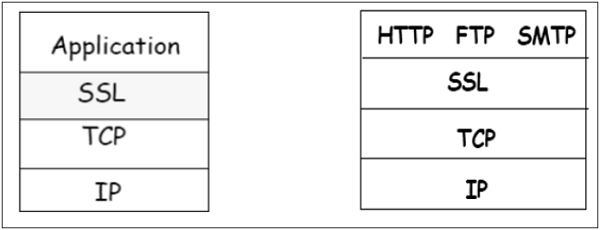
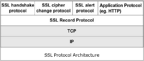
SSL itself is not a single layer protocol as depicted in the image; in fact it is composed of two sub-layers.
- Lower sub-layer comprises of the one component of SSL protocol called as SSL Record Protocol. This component provides integrity and confidentiality services.
- Upper sub-layer comprises of three SSL-related protocol components and an application protocol. Application component provides the information transfer service between client/server interactions. Technically, it can operate on top of SSL layer as well. Three SSL related protocol components are −
- SSL Handshake Protocol
- Change Cipher Spec Protocol
- Alert Protocol.
- These three protocols manage all of SSL message exchanges and are discussed later in this section.
Functions of SSL Protocol Components
The four sub-components of the SSL protocol handle various tasks for secure communication between the client machine and the server.
- Record Protocol
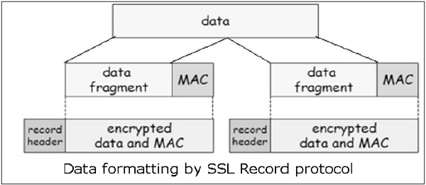
- The record layer formats the upper layer protocol messages.
- It fragments the data into manageable blocks (max length 16 KB). It optionally compresses the data.
- Encrypts the data.
- Provides a header for each message and a hash (Message Authentication Code (MAC)) at the end.
- Hands over the formatted blocks to TCP layer for transmission.
- SSL Handshake Protocol
- It is the most complex part of SSL. It is invoked before any application data is transmitted. It creates SSL sessions between the client and the server.
- Establishment of session involves Server authentication, Key and algorithm negotiation, Establishing keys and Client authentication (optional).
- A session is identified by unique set of cryptographic security parameters.
- Multiple secure TCP connections between a client and a server can share the same session.
- Handshake protocol actions through four phases. These are discussed in the next section.
- ChangeCipherSpec Protocol
- Simplest part of SSL protocol. It comprises of a single message exchanged between two communicating entities, the client and the server.
- As each entity sends the ChangeCipherSpec message, it changes its side of the connection into the secure state as agreed upon.
- The cipher parameters pending state is copied into the current state.
- Exchange of this Message indicates all future data exchanges are encrypted and integrity is protected.
- SSL Alert Protocol
- This protocol is used to report errors – such as unexpected message, bad record MAC, security parameters negotiation failed, etc.
- It is also used for other purposes – such as notify closure of the TCP connection, notify receipt of bad or unknown certificate, etc.
Establishment of SSL Session
As discussed above, there are four phases of SSL session establishment. These are mainly handled by SSL Handshake protocol.
Phase 1 − Establishing security capabilities.
- This phase comprises of exchange of two messages – Client_hello and Server_hello.
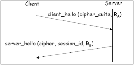
- Client_hello contains of list of cryptographic algorithms supported by the client, in decreasing order of preference.
- Server_hello contains the selected Cipher Specification (CipherSpec) and a new session_id.
- The CipherSpec contains fields like −
- Cipher Algorithm (DES, 3DES, RC2, and RC4)
- MAC Algorithm (based on MD5, SHA-1)
- Public-key algorithm (RSA)
- Both messages have “nonce” to prevent replay attack.
Phase 2 − Server authentication and key exchange.
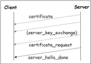
- Server sends certificate. Client software comes configured with public keys of various “trusted” organizations (CAs) to check certificate.
- Server sends chosen cipher suite.
- Server may request client certificate. Usually it is not done.
- Server indicates end of Server_hello.
Phase 3 − Client authentication and key exchange.
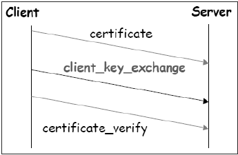
- Client sends certificate, only if requested by the server.
- It also sends the Pre-master Secret (PMS) encrypted with the server’s public key.
- Client also sends Certificate_verify message if certificate is sent by him to prove he has the private key associated with this certificate. Basically, the client signs a hash of the previous messages.
Phase 4 − Finish.
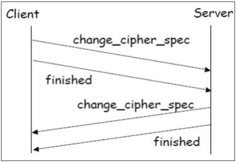
- Client and server send Change_cipher_spec messages to each other to cause the pending cipher state to be copied into the current state.
- From now on, all data is encrypted and integrity protected.
- Message “Finished” from each end verifies that the key exchange and authentication processes were successful.
All four phases, discussed above, happen within the establishment of TCP session. SSL session establishment starts after TCP SYN/ SYNACK and finishes before TCP Fin.
Resuming a Disconnected Session
- It is possible to resume a disconnected session (through Alertmessage), if the client sends a hello_request to the server with the encrypted session_id information.
- The server then determines if the session_id is valid. If validated, it exchanges ChangeCipherSpec and finished messages with the client and secure communications resume.
- This avoids recalculating of session cipher parameters and saves computing at the server and the client end.
SSL Session Keys
We have seen that during Phase 3 of SSL session establishment, a pre-master secret is sent by the client to the server encrypted using server’s public key. The master secret and various session keys are generated as follows −
- The master secret is generated (via pseudo random number generator) using −
- The pre-master secret.
- Two nonces (RA and RB) exchanged in the client_hello and server_hello messages.
- Six secret values are then derived from this master secret as −
- Secret key used with MAC (for data sent by server)
- Secret key used with MAC (for data sent by client)
- Secret key and IV used for encryption (by server)
- Secret key and IV used for encryption (by client)
TLS Protocol
In order to provide an open Internet standard of SSL, IETF released The Transport Layer Security (TLS) protocol in January 1999. TLS is defined as a proposed Internet Standard in RFC 5246.
Salient Features
- TLS protocol has same objectives as SSL.
- It enables client/server applications to communicate in a secure manner by authenticating, preventing eavesdropping and resisting message modification.
- TLS protocol sits above the reliable connection-oriented transport TCP layer in the networking layers stack.
- The architecture of TLS protocol is similar to SSLv3 protocol. It has two sub protocols: the TLS Record protocol and the TLS Handshake protocol.
- Though SSLv3 and TLS protocol have similar architecture, several changes were made in architecture and functioning particularly for the handshake protocol.
Comparison of TLS and SSL Protocols
There are main eight differences between TLS and SSLv3 protocols. These are as follows −
- Protocol Version − The header of TLS protocol segment carries the version number 3.1 to differentiate between number 3 carried by SSL protocol segment header.
- Message Authentication − TLS employs a keyed-hash message authentication code (H-MAC). Benefit is that H-MAC operates with any hash function, not just MD5 or SHA, as explicitly stated by the SSL protocol.
- Session Key Generation − There are two differences between TLS and SSL protocol for generation of key material.
- Method of computing pre-master and master secrets is similar. But in TLS protocol, computation of master secret uses the HMAC standard and pseudorandom function (PRF) output instead of ad-hoc MAC.
- The algorithm for computing session keys and initiation values (IV) is different in TLS than SSL protocol.
- Alert Protocol Message −
- TLS protocol supports all the messages used by the Alert protocol of SSL, except No certificate alert message being made redundant. The client sends empty certificate in case client authentication is not required.
- Many additional Alert messages are included in TLS protocol for other error conditions such as record_overflow, decode_error etc.
- Supported Cipher Suites − SSL supports RSA, Diffie-Hellman and Fortezza cipher suites. TLS protocol supports all suits except Fortezza.
- Client Certificate Types − TLS defines certificate types to be requested in a certificate_request message. SSLv3 support all of these. Additionally, SSL support certain other types of certificate such as Fortezza.
- CertificateVerify and Finished Messages −
- In SSL, complex message procedure is used for the certificate_verify message. With TLS, the verified information is contained in the handshake messages itself thus avoiding this complex procedure.
- Finished message is computed in different manners in TLS and SSLv3.
- Padding of Data − In SSL protocol, the padding added to user data before encryption is the minimum amount required to make the total data-size equal to a multiple of the cipher’s block length. In TLS, the padding can be any amount that results in data-size that is a multiple of the cipher’s block length, up to a maximum of 255 bytes.
The above differences between TLS and SSLv3 protocols are summarized in the following table.

Secure Browsing - HTTPS
In this section, we will discuss the use of SSL/TLS protocol for performing secure web browsing.
HTTPS Defined
Hyper Text Transfer Protocol (HTTP) protocol is used for web browsing. The function of HTTPS is similar to HTTP. The only difference is that HTTPS provides “secure” web browsing. HTTPS stands for HTTP over SSL. This protocol is used to provide the encrypted and authenticated connection between the client web browser and the website server.
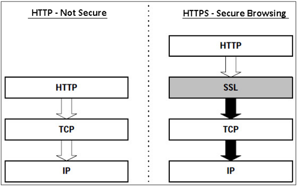
The secure browsing through HTTPS ensures that the following content are encrypted −
- URL of the requested web page.
- Web page contents provided by the server to the user client.
- Contents of forms filled in by user.
- Cookies established in both directions.
Working of HTTPS
HTTPS application protocol typically uses one of two popular transport layer security protocols - SSL or TLS. The process of secure browsing is described in the following points.
- You request a HTTPS connection to a webpage by entering https:// followed by URL in the browser address bar.
- Web browser initiates a connection to the web server. Use of https invokes the use of SSL protocol.
- An application, browser in this case, uses the system port 443 instead of port 80 (used in case of http).
- The SSL protocol goes through a handshake protocol for establishing a secure session as discussed in earlier sections.
- The website initially sends its SSL Digital certificate to your browser. On verification of certificate, the SSL handshake progresses to exchange the shared secrets for the session.
- When a trusted SSL Digital Certificate is used by the server, users get to see a padlock icon in the browser address bar. When an Extended Validation Certificate is installed on a website, the address bar turns green.

- Once established, this session consists of many secure connections between the web server and the browser.
Use of HTTPS
- Use of HTTPS provides confidentiality, server authentication and message integrity to the user. It enables safe conduct of e-commerce on the Internet.
- Prevents data from eavesdropping and denies identity theft which are common attacks on HTTP.
Present day web browsers and web servers are equipped with HTTPS support. The use of HTTPS over HTTP, however, requires more computing power at the client and the server end to carry out encryption and SSL handshake.
Secure Shell Protocol (SSH)
The salient features of SSH are as follows −
- SSH is a network protocol that runs on top of the TCP/IP layer. It is designed to replace the TELNET which provided unsecure means of remote logon facility.
- SSH provides a secure client/server communication and can be used for tasks such as file transfer and e-mail.
- SSH2 is a prevalent protocol which provides improved network communication security over earlier version SSH1.
SSH Defined
SSH is organized as three sub-protocols.
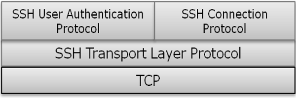
- Transport Layer Protocol − This part of SSH protocol provides data confidentiality, server (host) authentication, and data integrity. It may optionally provide data compression as well.
- Server Authentication − Host keys are asymmetric like public/private keys. A server uses a public key to prove its identity to a client. The client verifies that contacted server is a “known” host from the database it maintains. Once the server is authenticated, session keys are generated.
- Session Key Establishment − After authentication, the server and the client agree upon cipher to be used. Session keys are generated by both the client and the server. Session keys are generated before user authentication so that usernames and passwords can be sent encrypted. These keys are generally replaced at regular intervals (say, every hour) during the session and are destroyed immediately after use.
- Data Integrity − SSH uses Message Authentication Code (MAC) algorithms to for data integrity check. It is an improvement over 32 bit CRC used by SSH1.
- User Authentication Protocol − This part of SSH authenticates the user to the server. The server verifies that access is given to intended users only. Many authentication methods are currently used such as, typed passwords, Kerberos, public-key authentication, etc.
- Connection Protocol − This provides multiple logical channels over a single underlying SSH connection.
SSH Services
SSH provides three main services that enable provision of many secure solutions. These services are briefly described as follows −
- Secure Command-Shell (Remote Logon) − It allows the user to edit files, view the contents of directories, and access applications on connected device. Systems administrators can remotely start/view/stop services and processes, create user accounts, and change file/directories permissions and so on. All tasks that are feasible at a machine’s command prompt can now be performed securely from the remote machine using secure remote logon.
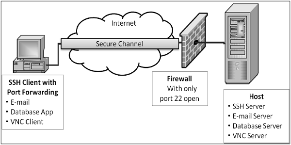
- Secure File Transfer − SSH File Transfer Protocol (SFTP) is designed as an extension for SSH-2 for secure file transfer. In essence, it is a separate protocol layered over the Secure Shell protocol to handle file transfers. SFTP encrypts both the username/password and the file data being transferred. It uses the same port as the Secure Shell server, i.e. system port no 22.
- Port Forwarding (Tunneling) − It allows data from unsecured TCP/IP based applications to be secured. After port forwarding has been set up, Secure Shell reroutes traffic from a program (usually a client) and sends it across the encrypted tunnel to the program on the other side (usually a server). Multiple applications can transmit data over a single multiplexed secure channel, eliminating the need to open many ports on a firewall or router.
Benefits & Limitations
The benefits and limitations of employing communication security at transport layer are as follows −
- Benefits
- Transport Layer Security is transparent to applications.
- Server is authenticated.
- Application layer headers are hidden.
- It is more fine-grained than security mechanisms at layer 3 (IPsec) as it works at the transport connection level.
- Limitations
- Applicable to TCP-based applications only (not UDP).
- TCP/IP headers are in clear.
- Suitable for direct communication between the client and the server. Does not cater for secure applications using chain of servers (e.g. email)
- SSL does not provide non-repudiation as client authentication is optional.
- If needed, client authentication needs to be implemented above SSL.
Summary
A large number of web applications have emerged on the Internet in the past decade. Many e-Governance and e-Commerce portal have come online. These applications require that session between the server and the client is secure providing confidentiality, authentication and integrity of sessions.
One way of mitigating a potential attack during a user’s session is to use a secure communication protocol. Two of such communication protocols, Secure Sockets Layer (SSL) and Transport Layer Security (TLS), are discussed in this chapter. Both of these protocol function at Transport layer.
Another transport layer protocol, Secure Shell (SSH), designed to replace the TELNET, provides secure means of remote logon facility. It is capable of providing various services such as Secure Command Shell and SFTP.
Employment of Transport layer security has many benefits. However, the security protocol designed at these layer can be used with TCP only. They do not provide security for communication implemented using UDP.
Network Security – Network Layer
Network layer security controls have been used frequently for securing communications, particularly over shared networks such as the Internet because they can provide protection for many applications at once without modifying them.
In the earlier chapters, we discussed that many real-time security protocols have evolved for network security ensuring basic tenets of security such as privacy, origin authentication, message integrity, and non-repudiation.
Most of these protocols remained focused at the higher layers of the OSI protocol stack, to compensate for inherent lack of security in standard Internet Protocol. Though valuable, these methods cannot be generalized easily for use with any application. For example, SSL is developed specifically to secure applications like HTTP or FTP. But there are several other applications which also need secure communications.
This need gave rise to develop a security solution at the IP layer so that all higher-layer protocols could take advantage of it. In 1992, the Internet Engineering Task Force (IETF) began to define a standard ‘IPsec’.
In this chapter, we will discuss how security is achieved at network layer using this very popular set of protocol IPsec.
Security in Network Layer
Any scheme that is developed for providing network security needs to be implemented at some layer in protocol stack as depicted in the diagram below −
| Layer | Communication Protocols | Security Protocols |
|---|---|---|
| Application Layer | HTTP FTP SMTP | PGP. S/MIME, HTTPS |
| Transport Layer | TCP /UDP | SSL, TLS, SSH |
| Network Layer | IP | IPsec |
The popular framework developed for ensuring security at network layer is Internet Protocol Security (IPsec).
Features of IPsec
- IPsec is not designed to work only with TCP as a transport protocol. It works with UDP as well as any other protocol above IP such as ICMP, OSPF etc.
- IPsec protects the entire packet presented to IP layer including higher layer headers.
- Since higher layer headers are hidden which carry port number, traffic analysis is more difficult.
- IPsec works from one network entity to another network entity, not from application process to application process. Hence, security can be adopted without requiring changes to individual user computers/applications.
- Tough widely used to provide secure communication between network entities, IPsec can provide host-to-host security as well.
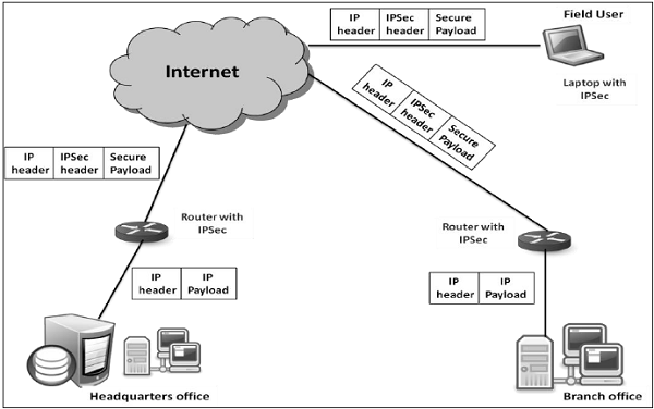
- The most common use of IPsec is to provide a Virtual Private Network (VPN), either between two locations (gateway-to-gateway) or between a remote user and an enterprise network (host-to-gateway).
Security Functions
The important security functions provided by the IPsec are as follows −
- Confidentiality
- Enables communicating nodes to encrypt messages.
- Prevents eavesdropping by third parties.
- Origin authentication and data integrity.
- Provides assurance that a received packet was actually transmitted by the party identified as the source in the packet header.
- Confirms that the packet has not been altered or otherwise.
- Key management.
- Allows secure exchange of keys.
- Protection against certain types of security attacks, such as replay attacks.
Virtual Private Network
Ideally, any institution would want its own private network for communication to ensure security. However, it may be very costly to establish and maintain such private network over geographically dispersed area. It would require to manage complex infrastructure of communication links, routers, DNS, etc.
IPsec provides an easy mechanism for implementing Virtual Private Network (VPN) for such institutions. VPN technology allows institution’s inter-office traffic to be sent over public Internet by encrypting traffic before entering the public Internet and logically separating it from other traffic. The simplified working of VPN is shown in the following diagram −
Overview of IPsec
IPsec is a framework/suite of protocols for providing security at the IP layer.
Origin
In early 1990s, Internet was used by few institutions, mostly for academic purposes. But in later decades, the growth of Internet became exponential due to expansion of network and several organizations using it for communication and other purposes.
With the massive growth of Internet, combined with the inherent security weaknesses of the TCP/IP protocol, the need was felt for a technology that can provide network security on the Internet. A report entitled "Security in the Internet Architecture” was issued by the Internet Architecture Board (IAB) in 1994. It identified the key areas for security mechanisms.
The IAB included authentication and encryption as essential security features in the IPv6, the next-generation IP. Fortunately, these security capabilities were defined such that they can be implemented with both the current IPv4 and futuristic IPv6.
Security framework, IPsec has been defined in several ‘Requests for comments’ (RFCs). Some RFCs specify some portions of the protocol, while others address the solution as a whole.
Operations Within IPsec
The IPsec suite can be considered to have two separate operations, when performed in unison, providing a complete set of security services. These two operations are IPsec Communication and Internet Key Exchange.
- IPsec Communication
- It is typically associated with standard IPsec functionality. It involves encapsulation, encryption, and hashing the IP datagrams and handling all packet processes.
- It is responsible for managing the communication according to the available Security Associations (SAs) established between communicating parties.
- It uses security protocols such as Authentication Header (AH) and Encapsulated SP (ESP).
- IPsec communication is not involved in the creation of keys or their management.
- IPsec communication operation itself is commonly referred to as IPsec.
- Internet Key Exchange (IKE)
- IKE is the automatic key management protocol used for IPsec.
- Technically, key management is not essential for IPsec communication and the keys can be manually managed. However, manual key management is not desirable for large networks.
- IKE is responsible for creation of keys for IPsec and providing authentication during key establishment process. Though, IPsec can be used for any other key management protocols, IKE is used by default.
- IKE defines two protocol (Oakley and SKEME) to be used with already defined key management framework Internet Security Association Key Management Protocol (ISAKMP).
- ISAKMP is not IPsec specific, but provides the framework for creating SAs for any protocol.
This chapter mainly discusses the IPsec communication and associated protocol employed to achieve security.
IPsec Communication Modes
IPsec Communication has two modes of functioning; transport and tunnel modes. These modes can be used in combination or used individually depending upon the type of communication desired.
Transport Mode
- IPsec does not encapsulate a packet received from upper layer.
- The original IP header is maintained and the data is forwarded based on the original attributes set by the upper layer protocol.
- The following diagram shows the data flow in the protocol stack.
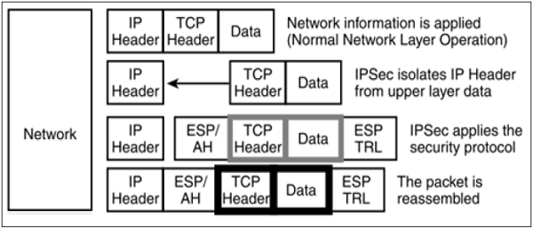
- The limitation of transport mode is that no gateway services can be provided. It is reserved for point-to-point communications as depicted in the following image.
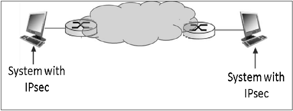
Tunnel Mode
- This mode of IPsec provides encapsulation services along with other security services.
- In tunnel mode operations, the entire packet from upper layer is encapsulated before applying security protocol. New IP header is added.
- The following diagram shows the data flow in the protocol stack.
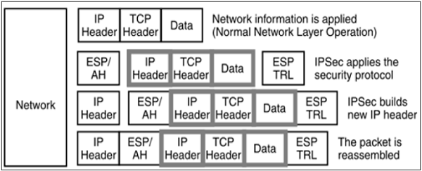
- Tunnel mode is typically associated with gateway activities. The encapsulation provides the ability to send several sessions through a single gateway.
- The typical tunnel mode communication is as depicted in the following diagram.

- As far as the endpoints are concerned, they have a direct transport layer connection. The datagram from one system forwarded to the gateway is encapsulated and then forwarded to the remote gateway. The remote associated gateway de-encapsulates the data and forwards it to the destination endpoint on the internal network.
- Using IPsec, the tunneling mode can be established between the gateway and individual end system as well.
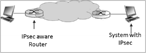
IPsec Protocols
IPsec uses the security protocols to provide desired security services. These protocols are the heart of IPsec operations and everything else is designed to support these protocol in IPsec.
Security associations between the communicating entities are established and maintained by the security protocol used.
There are two security protocols defined by IPsec — Authentication Header (AH) and Encapsulating Security Payload (ESP).
Authentication Header
The AH protocol provides service of data integrity and origin authentication. It optionally caters for message replay resistance. However, it does not provide any form of confidentiality.
AH is a protocol that provides authentication of either all or part of the contents of a datagram by the addition of a header. The header is calculated based on the values in the datagram. What parts of the datagram are used for the calculation, and where to place the header, depends on the mode cooperation (tunnel or transport).
The operation of the AH protocol is surprisingly simple. It can be considered similar to the algorithms used to calculate checksums or perform CRC checks for error detection.
The concept behind AH is the same, except that instead of using a simple algorithm, AH uses special hashing algorithm and a secret key known only to the communicating parties. A security association between two devices is set up that specifies these particulars.
The process of AH goes through the following phases.
- When IP packet is received from upper protocol stack, IPsec determine the associated Security Association (SA) from available information in the packet; for example, IP address (source and destination).
- From SA, once it is identified that security protocol is AH, the parameters of AH header are calculated. The AH header consists of the following parameters −
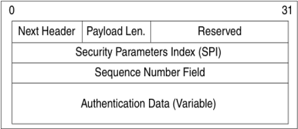
- The header field specifies the protocol of packet following AH header. Sequence Parameter Index (SPI) is obtained from SA existing between communicating parties.
- Sequence Number is calculated and inserted. These numbers provide optional capability to AH to resist replay attack.
- Authentication data is calculated differently depending upon the communication mode.
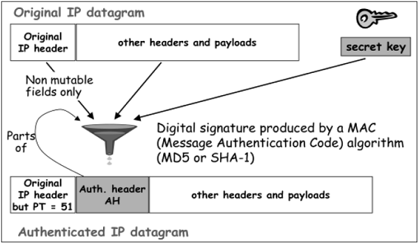
- In transport mode, the calculation of authentication data and assembling of final IP packet for transmission is depicted in the following diagram. In original IP header, change is made only in protocol number as 51 to indicated application of AH.
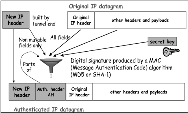
- In Tunnel mode, the above process takes place as depicted in the following diagram.
Encapsulation Security Protocol (ESP)
ESP provides security services such as confidentiality, integrity, origin authentication, and optional replay resistance. The set of services provided depends on options selected at the time of Security Association (SA) establishment.
In ESP, algorithms used for encryption and generating authenticator are determined by the attributes used to create the SA.
The process of ESP is as follows. The first two steps are similar to process of AH as stated above.
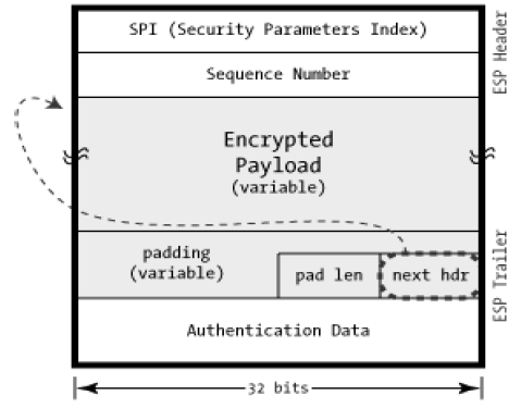
- Once it is determined that ESP is involved, the fields of ESP packet are calculated. The ESP field arrangement is depicted in the following diagram.
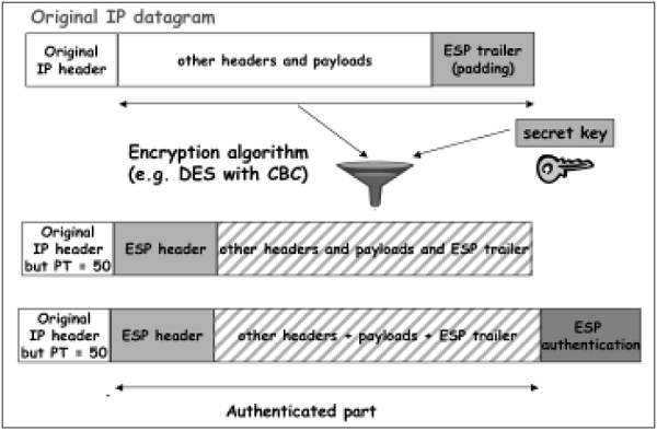
- Encryption and authentication process in transport mode is depicted in the following diagram.
- In case of Tunnel mode, the encryption and authentication process is as depicted in the following diagram.
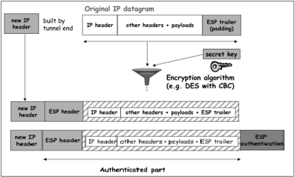
Although authentication and confidentiality are the primary services provided by ESP, both are optional. Technically, we can use NULL encryption without authentication. However, in practice, one of the two must be implemented to use ESP effectively.
The basic concept is to use ESP when one wants authentication and encryption, and to use AH when one wants extended authentication without encryption.
Security Associations in IPsec
Security Association (SA) is the foundation of an IPsec communication. The features of SA are −
- Before sending data, a virtual connection is established between the sending entity and the receiving entity, called “Security Association (SA)”.
- IPsec provides many options for performing network encryption and authentication. Each IPsec connection can provide encryption, integrity, authenticity, or all three services. When the security service is determined, the two IPsec peer entities must determine exactly which algorithms to use (for example, DES or 3DES for encryption; MD5 or SHA-1 for integrity). After deciding on the algorithms, the two devices must share session keys.
- SA is a set of above communication parameters that provides a relationship between two or more systems to build an IPsec session.
- SA is simple in nature and hence two SAs are required for bi-directional communications.
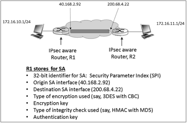
- SAs are identified by a Security Parameter Index (SPI) number that exists in the security protocol header.
- Both sending and receiving entities maintain state information about the SA. It is similar to TCP endpoints which also maintain state information. IPsec is connection-oriented like TCP.
Parameters of SA
Any SA is uniquely identified by the following three parameters −
- Security Parameters Index (SPI).
- It is a 32-bit value assigned to SA. It is used to distinguish among different SAs terminating at the same destination and using the same IPsec protocol.
- Every packet of IPsec carries a header containing SPI field. The SPI is provided to map the incoming packet to an SA.
- The SPI is a random number generated by the sender to identify the SA to the recipient.
- Destination IP Address − It can be IP address of end router.
- Security Protocol Identifier − It indicates whether the association is an AH or ESP SA.
Example of SA between two router involved in IPsec communication is shown in the following diagram.
Security Administrative Databases
In IPsec, there are two databases that control the processing of IPsec datagram. One is the Security Association Database (SAD) and the other is the Security Policy Database (SPD). Each communicating endpoint using IPsec should have a logically separate SAD and SPD.
Security Association Database
In IPsec communication, endpoint holds SA state in Security Association Database (SAD). Each SA entry in SAD database contains nine parameters as shown in the following table −
| S.No. | Parameters & Description |
|---|---|
| 1 |
Sequence Number Counter
For outbound communications. This is the 32-bit sequence number provided in the AH or ESP headers.
|
| 2 |
Sequence Number Overflow Counter
Sets an option flag to prevent further communications utilizing the specific SA
|
| 3 |
32-bit anti-replay window
Used to determine whether an inbound AH or ESP packet is a replay
|
| 4 |
Lifetime of the SA
Time till SA remain active
|
| 5 |
Algorithm - AH
Used in the AH and the associated key
|
| 6 |
Algorithm - ESP Auth
Used in the authenticating portion of the ESP header
|
| 7 |
Algorithm - ESP Encryption
Used in the encryption of the ESP and its associated key information
|
| 8 |
IPsec mode of operation
Transport or tunnel mode
|
| 9 |
Path MTU(PMTU)
Any observed path maximum transmission unit (to avoid fragmentation)
|
All SA entries in the SAD are indexed by the three SA parameters: Destination IP address, Security Protocol Identifier, and SPI.
Security Policy Database
SPD is used for processing outgoing packets. It helps in deciding what SAD entries should be used. If no SAD entry exists, SPD is used to create new ones.
Any SPD entry would contain −
- Pointer to active SA held in SAD.
- Selector fields – Field in incoming packet from upper layer used to decide application of IPsec. Selectors can include source and destination address, port numbers if relevant, application IDs, protocols, etc.
Outgoing IP datagrams go from the SPD entry to the specific SA, to get encoding parameters. Incoming IPsec datagram get to the correct SA directly using the SPI/DEST IP/Protocol triple, and from there extracts the associated SAD entry.
SPD can also specify traffic that should bypass IPsec. SPD can be considered as a packet filter where the actions decided upon are the activation of SA processes.
Summary
IPsec is a suite of protocols for securing network connections. It is rather a complex mechanism, because instead of giving straightforward definition of a specific encryption algorithm and authentication function, it provides a framework that allows an implementation of anything that both communicating ends agree upon.
Authentication Header (AH) and Encapsulating Security Payload (ESP) are the two main communication protocols used by IPsec. While AH only authenticate, ESP can encrypt and authenticate the data transmitted over the connection.
Transport Mode provides a secure connection between two endpoints without changing the IP header. Tunnel Mode encapsulates the entire payload IP packet. It adds new IP header. The latter is used to form a traditional VPN, as it provides a virtual secure tunnel across an untrusted Internet.
Setting up an IPsec connection involves all kinds of crypto choices. Authentication is usually built on top of a cryptographic hash such as MD5 or SHA-1. Encryption algorithms are DES, 3DES, Blowfish, and AES being common. Other algorithms are possible too.
Both communicating endpoints need to know the secret values used in hashing or encryption. Manual keys require manual entry of the secret values on both ends, presumably conveyed by some out-of-band mechanism, and IKE (Internet Key Exchange) is a sophisticated mechanism for doing this online.
Network Security – Data Link Layer
We have seen that rapid growth of Internet has raised a major concern for network security. Several methods have been developed to provide security in the application, transport, or network layer of a network.
Many organizations incorporate security measures at higher OSI layers, from application layer all the way down to IP layer. However, one area generally left unattended is hardening of Data Link layer. This can open the network to a variety of attacks and compromises.
In this chapter, we will discuss security problems at Data Link Layer and methods to counter them. Our discussion will be focused on Ethernet network.
Security Concerns in Data Link Layer
Data link Layer in Ethernet networks is highly prone to several attacks. The most common attacks are −
ARP Spoofing
Address Resolution Protocol (ARP) is a protocol used to map an IP address to a physical machine address recognizable in the local Ethernet. When a host machine needs to find a physical Media Access Control (MAC) address for an IP address, it broadcasts an ARP request. The other host that owns the IP address sends an ARP reply message with its physical address.
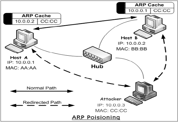
Each host machine on network maintains a table, called ‘ARP cache’. The table holds the IP address and associated MAC addresses of other host on the network.
Since ARP is a stateless protocol, every time a host gets an ARP reply from another host, even though it has not sent an ARP request, it accepts that ARP entry and updates its ARP cache. The process of modifying a target host’s ARP cache with a forged entry known as ARP poisoning or ARP spoofing.
ARP spoofing may allow an attacker to masquerade as legitimate host and then intercept data frames on a network, modify or stop them. Often the attack is used to launch other attacks such as man-in-the-middle, session hijacking, or denial of service.
MAC Flooding
Every switch in the Ethernet has a Content-Addressable Memory (CAM) table that stores the MAC addresses, switch port numbers, and other information. The table has a fixed size. In the MAC flooding attack, the attacker floods the switch with MAC addresses using forged ARP packets until the CAM table is full.
Once CAM is flooded, the switch goes into hub-like mode and starts broadcasting the traffic that do not have CAM entry. The attacker who is on the same network, now receives all the frames which were destined only for a specific host.
Port Stealing
Ethernet switches have the ability to learn and bind MAC addresses to ports. When a switch receives traffic from a port with a MAC source address, it binds the port number and that MAC address.
The port stealing attack exploits this ability of the switches. The attacker floods the switch with forged ARP frames with the target host’s MAC address as the source address. Switch is fooled to believe that the target host is on port, on which actually an attacker is connected.
Now all data frames intended for the targeted host are sent to the attacker’s switch port and not to the target host. Thus, the attacker now receives all the frames which were actually destined only for the target host.
DHCP Attacks
Dynamic Host Configuration Protocol (DHCP) is not a datalink protocol but solutions to DHCP attacks are also useful to thwart Layer 2 attacks.
DHCP is used to dynamically allocate IP addresses to computers for a specific time period. It is possible to attack DHCP servers by causing denial of service in the network or by impersonating the DHCP server. In a DHCP starvation attack, the attacker requests all of the available DHCP addresses. This results in a denial of service to the legitimate host on the network.
In DHCP spoofing attack, the attacker can deploy a rogue DHCP server to provide addresses to the clients. Here, the attacker can provide the host machines with a rouge default gateway with the DHCP responses. Data frames from the host are now guided to rouge gateway where the attacker can intercept all package and reply to actual gateway or drop them.
Other Attacks
In addition to above popular attacks, there are other attacks such as Layer 2-based broadcasting, Denial of Service (DoS), MAC cloning.
In the broadcasting attack, the attacker sends spoofed ARP replies to the hosts on the network. These ARP replies set the MAC address of the default gateway to the broadcast address. This causes all the outbound traffic to get broadcast, enabling sniffing by the attacker sitting on the same Ethernet. This type of attack also affects the network capacity.
In the Layer 2-based DoS attacks, the attacker updates the ARP caches of hosts in the network with non-existent MAC addresses. The MAC address of each network interface card in a network is supposed to be globally unique. However, it can easily be changed by enabling MAC cloning. The attacker disables the target host through DoS attack and then uses the IP and MAC addresses of the targeted host.
The attacker executes the attacks to launch the higher level attacks in order to jeopardize the security of information traveling on network. He can intercept all the frames and would be able to read the frame data. The attacker can act as a man-in-middle and modify data or simply drop the frame leading to DoS. He can hijack the ongoing session between the target host and other machines, and communicate wrong information altogether.
Securing Ethernet LANs
We discussed some widely known attacks at Data Link Layer in the previous section. Several methods have been developed to mitigate these types of attacks. Some of the important methods are −
Port Security
It is a layer 2 security feature available on intelligent Ethernet switches. It involves tying a physical port of a switch to a specific MAC address/es. Anyone can access an unsecure network by simply connecting the host to one of the available switch ports. But, port security can secure layer 2 access.
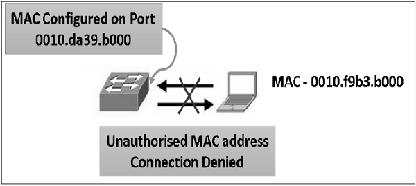
By default, port security limits the ingress MAC address count to one. However, it is possible to allow more than one authorized host to connect from that port through configuration. Allowed MAC addresses per interface can be statically configured. A convenient alternative is to enable "sticky" MAC address learning where MAC addresses will be dynamically learned by switch port until the maximum limit for the port is reached.
To ensure security, reaction to the change in the specified MAC address/es on a port or excess addresses on a port can be controlled in many different ways. The port can be configured to shut down or block the MAC addresses that exceed a specified limit. The recommended best practice is to shut down the port. Port security prevents MAC flooding and cloning attacks.
DHCP Snooping
We have seen that DHCP spoofing is an attack where the attacker listens for DHCP requests from host on the network and answers them with fake DHCP response before the authorized DHCP response comes to the host.
DHCP snooping can prevent such attacks. DHCP snooping is a switch feature. Switch can be configured to determine which switch ports can respond to DHCP requests. Switch ports are identified as trusted or untrusted ports.
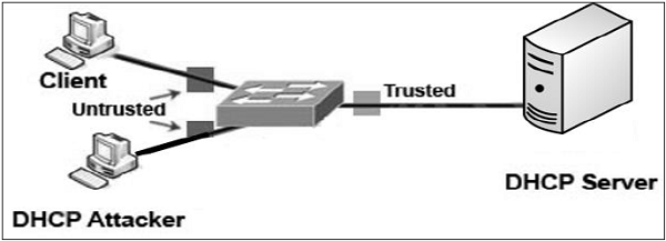
Only ports that connect to an authorized DHCP server are configured as “trusted”, and allowed to send all types of DHCP messages. All other ports on the switch are untrusted and can send only DHCP requests. If a DHCP response is seen on an untrusted port, the port is shut down.
Preventing ARP Spoofing
The method of port security can prevent MAC flooding and cloning attacks. However, it does not prevent ARP spoofing. Port security validates the MAC source address in the frame header, but ARP frames contain an additional MAC source field in the data payload, and the host uses this field to populate their ARP cache. Some methods to prevent ARP spoofing are listed as follows.
- Static ARP − One of the recommended action is to employ static ARP entries in the host ARP table. Static ARP entries are permanent entries in an ARP cache. However, this method is impractical. Also, it does not allow the use of some Dynamic Host Configuration Protocol (DHCP) as static IP needs to be used for all host in the layer 2 network.
- Intrusion Detection System − The method of defense is to utilize Intrusion Detection System (IDS) configured to detect high amounts of ARP traffic. However, IDS is prone to reporting false positives.
- Dynamic ARP Inspection − This method of preventing ARP spoofing is similar to DHCP snooping. It uses trusted and untrusted ports. ARP replies are allowed into the switch interface only on trusted ports. If an ARP reply comes to the switch on an untrusted port, the contents of the ARP reply packet is compared to the DHCP binding table to verify its accuracy. If the ARP reply is not valid, the ARP reply is dropped, and the port is disabled.
Securing Spanning Tree Protocol
Spanning Tree Protocol (STP) is a layer 2 link management protocol. The main purpose of STP is to ensure that there are no data flow loops when network has redundant paths. Generally, redundant paths are built to provide reliability to the network. But they can form deadly loops which can lead to DoS attack in the network.
Spanning Tree Protocol
In order to provide desired path redundancy, as well as to avoid a loop condition, STP defines a tree that spans all the switches in a network. STP forces certain redundant data links into a blocked state and keeps other links in a forwarding state.
If a link in the forwarding state breaks down, STP reconfigures the network and redefines data paths by activating appropriate standby path. STP runs on bridges and switches deployed in the network. All the switches exchange information for root switch selection and for subsequent configuration of the network. Bridge Protocol Data Units (BPDUs) carry this information. Through exchange of BPDUs, all the switches in the network elect a root bridge/switch that becomes the focal point in the network and controls the blocked and forwarded links.
Attacks on STP
- Taking Over the Root Bridge. It is one of the most disruptive type of attack at layer 2. By default, a LAN switch takes any BPDU sent from neighboring switch at face value. Incidentally, STP is trustful, stateless, and does not provide any sound authentication mechanism.
- Once in root attack mode, the attacking switch sends a BPDU every 2 sec with the same priority as the current root bridge, but with a slightly numerically lower MAC address, which ensures its victory in the root-bridge election process. The attacker switch can launch DoS attack either by not properly acknowledging other switches causing BPDU flooding or by subjecting switches to over-process BPDUS by claiming to be root at one time and retracting in quick succession.
- DoS using Flood of Configuration BPDU. The attacking switch does not attempt to take over as root. Instead, it generates large number of BPDUs per second leading to very high CPU utilization on the switches.
Preventing Attacks on STP
Fortunately, the countermeasure to a root takeover attack is simple and straightforward. Two features help in defeating a root takeover attack.
- Root Guard − Root guard restricts the switch ports out of which the root bridge may be negotiated. If a ‘root-guard-enabled’ port receives BPDUs that are superior to those that the current root bridge is sending, then that port is moved to a root-inconsistent state, and no data traffic is forwarded across that port. Root guard is best deployed toward ports that connect to switches which are not expected to take over as the root bridge.
- BPDU-Guard − BPDU guard is used to protect the network from the problems that may be caused by the receipt of BPDUs on access ports. These are the ports that should not be receiving them. BPDU guard is best deployed toward user-facing ports to prevent insertion of rogue switch by an attacker.
Securing Virtual LAN
In local networks, Virtual Local Area Networks (VLANs) are sometimes configured as a security measure to limit the number of hosts susceptible to layer 2 attacks. VLANs create network boundaries, over which broadcast (ARP, DHCP) traffic cannot cross.
Virtual Local Area Network
A network employing switch/es supporting VLAN capabilities can be configured to define multiple VLANs over a single physical LAN infrastructure.
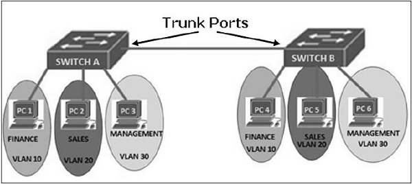
The common form of VLAN is a port-based VLAN. In this VLAN structure, the switch ports are grouped into VLAN using switch management software. Thus a single physical switch can act as multiple virtual switches.
Employment of VLANs provide traffic isolation. It divides the large broadcast layer 2 network into smaller logical layer 2 networks and thus reduces the scope of attacks such as ARP/DHCP Spoofing. Data frames of one VLAN can move from/to within ports belonging to the same VLAN only. The frames forwarding between two VLANs is done through routing.
VLANs generally span multiple switches as shown in the diagram above. The link between trunk ports carry frames of all VLANs defined over multiple physical switches. Hence, VLAN frames forwarded between switches can’t be simple IEEE 802.1 Ethernet format frames. Since, these frame move on same physical link, they now need to carry VLAN ID information. IEEE 802.1Q protocol adds/removes additional header fields to plain Ethernet frames forwarded between trunk ports.

When the field following the two IP addresses fields is 0x8100 (> 1500), the frame is identified as 802.1Q frame. Value of 2-byte Tag Protocol Identifier (TPI) is 81-00. TCI field consist of 3-bit priority information, 1-bit Drop eligible indicator (DEI), and 12-bit VLAN ID. This 3-bit priority field and DEI field are not relevant to VLANs. Priority bits are used for provision of Quality of Service.
When a frame does not belong to any VLAN, there is a default VLAN id which the frame is considered to be associated with.
Attack on VLAN & Prevention Measures
In a VLAN hopping attack, an attacker on one VLAN can gain access to the traffic on other VLANs that would normally not be accessible. It would bypass a layer 3 device (router) when communicating from one VLAN to another, thus defeating the purpose of VLAN creation.
VLAN hopping can be performed by two methods; switch spoofing and double tagging.
Switch Spoofing
It can occur when the switch port, to which the attacker is connected, is either in ‘trunking’ mode or ‘auto-negotiation’ mode. The attacker acts as a switch and adds 802.1Q encapsulation headers with VLAN tags for target remote VLANs to its outgoing frames. The receiving switch interprets those frames as sourced from another 802.1Q switch, and forwards the frames into the target VLAN.
The two preventive measures against switch spoofing attacks are to set edge ports to static access mode and to disable auto-negotiation on all ports.
Double Tagging
In this attack, an attacker connected on native VLAN port of switch prepends two VLAN tags in the frame header. The first tag is of native VLAN and second is for target VLAN. When the first switch receives the attacker’s frames, it removes the first tag since frames of native VLAN are forwarded without tag on trunk port.
- Since the second tag was never removed by the first switch, the receiving switch identifies the remaining tag as the VLAN destination and forwards the frames to the target host in that VLAN. The double tagging attack exploits the concept of native VLAN. Since VLAN 1 is the default VLAN for access ports and the default native VLAN on trunks, it’s an easy target.
- The first prevention measure is to remove all access ports from the default VLAN 1 since the attacker’s port must match that of the switch’s native VLAN. The second prevention measure is to assign the native VLAN on all switch trunks to some unused VLAN, say VLAN id 999. And lastly, all switches be configured to carry out explicit tagging of native VLAN frames on the trunk port.
Securing Wireless LAN
Wireless local area network is a network of wireless nodes within a limited geographic area, such as an office building or school campus. Nodes are capable of radio communication.
Wireless LAN
Wireless LAN is usually implemented as extensions of existing wired LAN to provide network access with device mobility. The most widely implemented wireless LAN technologies are based on the IEEE 802.11 standard and its amendments.
The two main components in wireless LAN are −
- Access Points (APs) − These are base stations for the wireless network. They transmit and receive radio frequencies to communicate with wireless clients.
- Wireless Clients − These are computing devices that are equipped with a Wireless Network Interface Card (WNIC). Laptops, IP Phones, PDAs are typical examples of wireless clients.
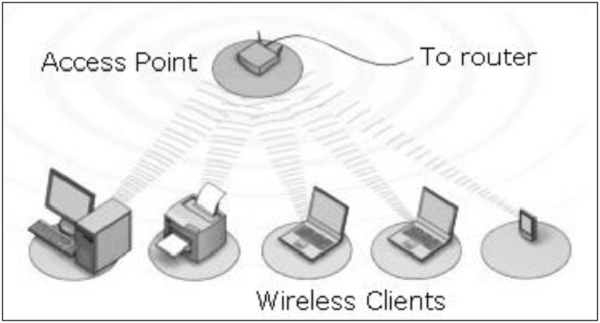
Many organizations have implemented wireless LANs. These networks are growing phenomenally. It is thus, crucial to understand threats in wireless LANs and learn the common preventive measure to ensure network security.
Attacks in Wireless LAN
The typical attacks that are carried out on Wireless LAN are −
- Eavesdropping − The attacker passively monitors wireless networks for data, including authentication credentials.
- Masquerading − The attacker impersonates an authorized user and gains access and privileges on wireless networks.
- Traffic Analysis − The attacker monitors transmissions via wireless networks to identify communication patterns and participants.
- Denial of Service − The attacker prevents or restricts the normal use or management of wireless LAN or network devices.
- Message Modification/Replay − The attacker alters or replies to a legitimate message sent via wireless networks by deleting, adding to, changing, or reordering it.
Security Measures in Wireless LAN
Security measures provide means to defeat attacks and manage risks to the networks. These are network management, operation, and technical measures. We describe below the technical measures adopted to ensure confidentiality, availability, and integrity of data transmitted via wireless LANs.
In wireless LANs, all APs should be configured to provide security through encryption and client authentication. The types of schemes used in Wireless LAN to provide security are as follows −
Wired Equivalent Privacy (WEP)
It is an encryption algorithm built into the 802.11 standard to secure wireless networks. WEP encryption uses the RC4 (Rivest Cipher 4) stream cipher with 40-bit/104-bit keys and a 24-bit initialization vector. It can also provide endpoint authentication.
It is, however, the weakest encryption security mechanism, as a number of flaws have been discovered in WEP encryption. WEP also does not have authentication protocol. Hence, using WEP is not highly recommended.
802.11i Protocol
In this protocol numerous and stronger forms of encryption are possible. It has been developed to replace weak WEP scheme. It provides key distribution mechanism. It supports one key per station, and does not use the same key for all. It uses authentication server separate from the access point.
IEEE802.11i mandates the use of a protocol named Counter mode with CBC-MAC Protocol (CCMP). CCMP provides confidentiality and integrity of the data transferred and authenticity of the sender. It is based on the Advanced Encryption Standard (AES) block cipher.
The IEEE802.11i protocol has four phases of operation.

- STA and AP communicate and discover mutual security capabilities such as supported algorithms.
- STA and AS mutually authenticate and together generate Master Key (MK). AP acts as “pass through”.
- STA derives Pairwise Master Key (PMK). AS derives same PMK and sends to AP.
- STA, AP use PMK to derive Temporal Key (TK) to be used for message encryption and data integrity.
Other Standards
- Wi-Fi Protected Access (WPA) − This protocol implements the majority of the IEEE 802.11i standard. It existed before IEEE 802.11i and uses RC4 algorithm for encryption. It has two modes of operation. In ‘Enterprise’ mode, WPA uses authentication protocol 802.1x to communicate with authentication server, and hence pre-master keys (PMK) is specific to client station. In ‘Personal’ mode, it does not use 802.1x, PMK is replaced by a pre-shared key, as used for Small Office Home Office (SOHO) wireless LAN environments.WPA also includes a sound message integrity check replacing the Cyclic Redundancy Check (CRC) that was used by the WEP standard.
- WPA2 − WPA2 replaced the WPA. WPA2 implements all mandatory elements of IEEE 802.11i scheme. In particular, it includes mandatory support for CCMP, an AES-based encryption mode with strong security. Thus, as far as the attacks are concerned, WPA2 / IEEE802.11i provides adequate solutions to defend against WEP weaknesses, man-in-the-middle attacks, forgery packets forgery, and replay attacks. However, DoS attack is not addressed properly and there are no solid protocols to stop such attacks basically because such attacks target the physical layer like interfering with the frequency band.
Summary
In this chapter, we considered attacks and mitigation techniques assuming a switched Ethernet network running IP. If your network does not use Ethernet as layer 2 protocol, some of these attacks may not be applicable, but chances are such network is vulnerable to different types of attacks.
Security is only as strong as the weakest link. When it comes to networking, layer 2 can be a very weak link. Layer 2 security measures mentioned in this chapter go a long way towards protecting a network from many types of attacks.
Network Security – Access Control
Network access control is a method of enhancing the security of a private organizational network by restricting the availability of network resources to endpoint devices that comply with the organization’s security policy. A typical network access control scheme comprises of two major components such as Restricted Access and Network Boundary Protection.
Restricted Access to the network devices is achieved through user authentication and authorization control which is responsible for identifying and authenticating different users to the network system. Authorization is the process of granting or denying specific access permissions to a protected resource.
Network Boundary Protection controls logical connectivity into and out of networks. For example, multiple firewalls can be deployed to prevent unauthorized access to the network systems. Also intrusion detection and prevention technologies can be deployed to defend against attacks from the Internet.
In this chapter, we will discuss the methods for user identification and authentication for network access followed by various types of firewalls and intrusion detection systems.
Securing Access to Network Devices
Restricting access to the devices on network is a very essential step for securing a network. Since network devices comprise of communication as well as computing equipment, compromising these can potentially bring down an entire network and its resources.
Paradoxically, many organizations ensure excellent security for their servers and applications but leave communicating network devices with rudimentary security.
An important aspect of network device security is access control and authorization. Many protocols have been developed to address these two requirements and enhance network security to higher levels.
User Authentication and Authorization
User authentication is necessary to control access to the network systems, in particular network infrastructure devices. Authentication has two aspects: general access authentication and functional authorization.
General access authentication is the method to control whether a particular user has “any” type of access right to the system he is trying to connect to. Usually, this kind of access is associated with the user having an “account” with that system. Authorization deals with individual user “rights”. For example, it decides what can a user do once authenticated; the user may be authorized to configure the device or only view the data.
User authentication depends up on factors that include something he knows (password), something he has (cryptographic token), or something he is (biometric). The use of more than one factor for identification and authentication provides the basis for Multifactor authentication.
Password Based Authentication
At a minimum level, all network devices should have username-password authentication. The password should be non-trivial (at least 10 character, mixed alphabets, numbers, and symbols).
In case of remote access by the user, a method should be used to ensure usernames and passwords are not passed in the clear over the network. Also, passwords should also be changed with some reasonable frequency.
Centralized Authentication Methods
Individual device based authentication system provides a basic access control measure. However, a centralized authentication method is considered more effective and efficient when the network has large number of devices with large numbers of users accessing these devices.
Traditionally, centralized authentication was used to solve problems faced in remote network access. In Remote Access Systems (RAS), the administration of users on the network devices is not practical. Placing all user information in all devices and then keeping that information up-to-date is an administrative nightmare.
Centralized authentication systems, such as RADIUS and Kerberos, solve this problem. These centralized methods allow user information to be stored and managed in one place. These systems can usually be seamlessly integrated with other user account management schemes such as Microsoft’s Active Directory or LDAP directories. Most RADIUS servers can communicate with other network devices in the normal RADIUS protocol and then securely access account information stored in the directories.
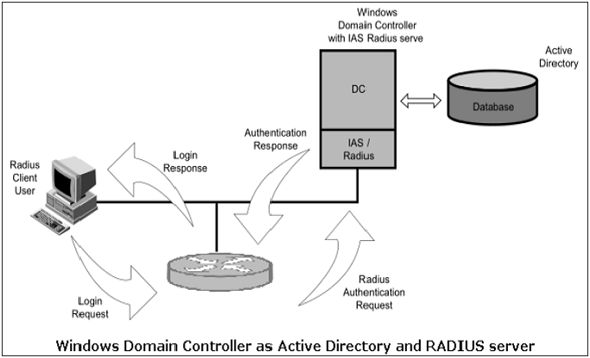
For example, Microsoft’s Internet Authentication Server (IAS) bridges RADIUS and Active Directory to provide centralized authentication for the users of devices. It also ensures that the user account information is unified with the Microsoft domain accounts. The above diagram shows a Windows Domain controller operating as both an Active Directory server and a RADIUS server for network elements to authenticate into an Active Directory domain.
Access Control Lists
Many network devices can be configured with access lists. These lists define hostnames or IP addresses that are authorized for accessing the device. It is typical, for instance, to restrict access to network equipment from IPs except for the network administrator.
This would then protect against any type of access that might be unauthorized. These types of access lists serve as an important last defense and can be quite powerful on some devices with different rules for different access protocols.
Network Security – Firewalls
Almost every medium and large-scale organization has a presence on the Internet and has an organizational network connected to it. Network partitioning at the boundary between the outside Internet and the internal network is essential for network security. Sometimes the inside network (intranet) is referred to as the “trusted” side and the external Internet as the “un-trusted” side.
Types of Firewall
Firewall is a network device that isolates organization’s internal network from larger outside network/Internet. It can be a hardware, software, or combined system that prevents unauthorized access to or from internal network.
All data packets entering or leaving the internal network pass through the firewall, which examines each packet and blocks those that do not meet the specified security criteria.

Deploying firewall at network boundary is like aggregating the security at a single point. It is analogous to locking an apartment at the entrance and not necessarily at each door.
Firewall is considered as an essential element to achieve network security for the following reasons −
- Internal network and hosts are unlikely to be properly secured.
- Internet is a dangerous place with criminals, users from competing companies, disgruntled ex-employees, spies from unfriendly countries, vandals, etc.
- To prevent an attacker from launching denial of service attacks on network resource.
- To prevent illegal modification/access to internal data by an outsider attacker.
Firewall is categorized into three basic types −
- Packet filter (Stateless & Stateful)
- Application-level gateway
- Circuit-level gateway
These three categories, however, are not mutually exclusive. Modern firewalls have a mix of abilities that may place them in more than one of the three categories.
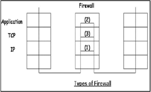
Stateless & Stateful Packet Filtering Firewall
In this type of firewall deployment, the internal network is connected to the external network/Internet via a router firewall. The firewall inspects and filters data packet-by-packet.
Packet-filtering firewalls allow or block the packets mostly based on criteria such as source and/or destination IP addresses, protocol, source and/or destination port numbers, and various other parameters within the IP header.
The decision can be based on factors other than IP header fields such as ICMP message type, TCP SYN and ACK bits, etc.
Packet filter rule has two parts −
- Selection criteria − It is a used as a condition and pattern matching for decision making.
- Action field − This part specifies action to be taken if an IP packet meets the selection criteria. The action could be either block (deny) or permit (allow) the packet across the firewall.
Packet filtering is generally accomplished by configuring Access Control Lists (ACL) on routers or switches. ACL is a table of packet filter rules.
As traffic enters or exits an interface, firewall applies ACLs from top to bottom to each incoming packet, finds matching criteria and either permits or denies the individual packets.
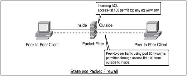
Stateless firewall is a kind of a rigid tool. It looks at packet and allows it if its meets the criteria even if it is not part of any established ongoing communication.
Hence, such firewalls are replaced by stateful firewalls in modern networks. This type of firewalls offer a more in-depth inspection method over the only ACL based packet inspection methods of stateless firewalls.
Stateful firewall monitors the connection setup and teardown process to keep a check on connections at the TCP/IP level. This allows them to keep track of connections state and determine which hosts have open, authorized connections at any given point in time.
They reference the rule base only when a new connection is requested. Packets belonging to existing connections are compared to the firewall's state table of open connections, and decision to allow or block is taken. This process saves time and provides added security as well. No packet is allowed to trespass the firewall unless it belongs to already established connection. It can timeout inactive connections at firewall after which it no longer admit packets for that connection.
Application Gateways
An application-level gateway acts as a relay node for the application-level traffic. They intercept incoming and outgoing packets, run proxies that copy and forward information across the gateway, and function as a proxy server, preventing any direct connection between a trusted server or client and an untrusted host.
The proxies are application specific. They can filter packets at the application layer of the OSI model.
Application-specific Proxies
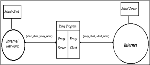
An application-specific proxy accepts packets generated by only specified application for which they are designed to copy, forward, and filter. For example, only a Telnet proxy can copy, forward, and filter Telnet traffic.
If a network relies only on an application-level gateway, incoming and outgoing packets cannot access services that have no proxies configured. For example, if a gateway runs FTP and Telnet proxies, only packets generated by these services can pass through the firewall. All other services are blocked.
Application-level Filtering
An application-level proxy gateway, examines and filters individual packets, rather than simply copying them and blindly forwarding them across the gateway. Application-specific proxies check each packet that passes through the gateway, verifying the contents of the packet up through the application layer. These proxies can filter particular kinds of commands or information in the application protocols.
Application gateways can restrict specific actions from being performed. For example, the gateway could be configured to prevent users from performing the ‘FTP put’ command. This can prevent modification of the information stored on the server by an attacker.
Transparent
Although application-level gateways can be transparent, many implementations require user authentication before users can access an untrusted network, a process that reduces true transparency. Authentication may be different if the user is from the internal network or from the Internet. For an internal network, a simple list of IP addresses can be allowed to connect to external applications. But from the Internet side a strong authentication should be implemented.
An application gateway actually relays TCP segments between the two TCP connections in the two directions (Client ↔ Proxy ↔ Server).
For outbound packets, the gateway may replace the source IP address by its own IP address. The process is referred to as Network Address Translation (NAT). It ensures that internal IP addresses are not exposed to the Internet.
Circuit-Level Gateway
The circuit-level gateway is an intermediate solution between the packet filter and the application gateway. It runs at the transport layer and hence can act as proxy for any application.
Similar to an application gateway, the circuit-level gateway also does not permit an end-to-end TCP connection across the gateway. It sets up two TCP connections and relays the TCP segments from one network to the other. But, it does not examine the application data like application gateway. Hence, sometime it is called as ‘Pipe Proxy’.
SOCKS
SOCKS (RFC 1928) refers to a circuit-level gateway. It is a networking proxy mechanism that enables hosts on one side of a SOCKS server to gain full access to hosts on the other side without requiring direct IP reachability. The client connects to the SOCKS server at the firewall. Then the client enters a negotiation for the authentication method to be used, and authenticates with the chosen method.
The client sends a connection relay request to the SOCKS server, containing the desired destination IP address and transport port. The server accepts the request after checking that the client meets the basic filtering criteria. Then, on behalf of the client, the gateway opens a connection to the requested untrusted host and then closely monitors the TCP handshaking that follows.
The SOCKS server informs the client, and in case of success, starts relaying the data between the two connections. Circuit level gateways are used when the organization trusts the internal users, and does not want to inspect the contents or application data sent on the Internet.
Firewall Deployment with DMZ
A firewall is a mechanism used to control network traffic ‘into’ and ‘out’ of an organizational internal network. In most cases these systems have two network interfaces, one for the external network such as the Internet and the other for the internal side.
The firewall process can tightly control what is allowed to traverse from one side to the other. An organization that wishes to provide external access to its web server can restrict all traffic arriving at firewall expect for port 80 (the standard http port). All other traffic such as mail traffic, FTP, SNMP, etc., is not allowed across the firewall into the internal network. An example of a simple firewall is shown in the following diagram.
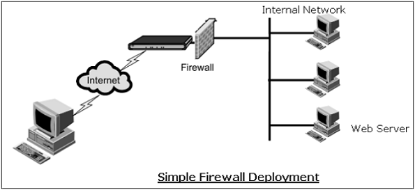
In the above simple deployment, though all other accesses from outside are blocked, it is possible for an attacker to contact not only a web server but any other host on internal network that has left port 80 open by accident or otherwise.
Hence, the problem most organizations face is how to enable legitimate access to public services such as web, FTP, and e-mail while maintaining tight security of the internal network. The typical approach is deploying firewalls to provide a Demilitarized Zone (DMZ) in the network.
In this setup (illustrated in following diagram), two firewalls are deployed; one between the external network and the DMZ, and another between the DMZ and the internal network. All public servers are placed in the DMZ.
With this setup, it is possible to have firewall rules which allow public access to the public servers but the interior firewall can restrict all incoming connections. By having the DMZ, the public servers are provided with adequate protection instead of placing them directly on external network.
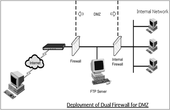
Intrusion Detection / Prevention System
The packet filtering firewalls operate based on rules involving TCP/UDP/IP headers only. They do not attempt to establish correlation checks among different sessions.
Intrusion Detection/Prevention System (IDS/IPS) carry out Deep Packet Inspection (DPI) by looking at the packet contents. For example, checking character strings in packet against database of known virus, attack strings.
Application gateways do look at the packet contents but only for specific applications. They do not look for suspicious data in the packet. IDS/IPS looks for suspicious data contained in packets and tries to examine correlation among multiple packets to identify any attacks such as port scanning, network mapping, and denial of service and so on.
Difference between IDS and IPS
IDS and IPS are similar in detection of anomalies in the network. IDS is a ‘visibility’ tool whereas IPS is considered as a ‘control’ tool.
Intrusion Detection Systems sit off to the side of the network, monitoring traffic at many different points, and provide visibility into the security state of the network. In case of reporting of anomaly by IDS, the corrective actions are initiated by the network administrator or other device on the network.
Intrusion Prevention System are like firewall and they sit in-line between two networks and control the traffic going through them. It enforces a specified policy on detection of anomaly in the network traffic. Generally, it drops all packets and blocks the entire network traffic on noticing an anomaly till such time an anomaly is addressed by the administrator.
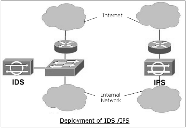
Types of IDS
There are two basic types of IDS.
- Signature-based IDS
- It needs a database of known attacks with their signatures.
- Signature is defined by types and order of packets characterizing a particular attack.
- Limitation of this type of IDS is that only known attacks can be detected. This IDS can also throw up a false alarm. False alarm can occur when a normal packet stream matches the signature of an attack.
- Well-known public open-source IDS example is “Snort” IDS.
- Anomaly-based IDS
- This type of IDS creates a traffic pattern of normal network operation.
- During IDS mode, it looks at traffic patterns that are statistically unusual. For example, ICMP unusual load, exponential growth in port scans, etc.
- Detection of any unusual traffic pattern generates the alarm.
- The major challenge faced in this type of IDS deployment is the difficulty in distinguishing between normal traffic and unusual traffic.
Summary
In this chapter, we discussed the various mechanisms employed for network access control. The approach to network security through access control is technically different than implementing security controls at different network layers discussed in the earlier chapters of this tutorial. However, though the approaches of implementation are different, they are complementary to each other.
Network access control comprises of two main components: user authentication and network boundary protection. RADIUS is a popular mechanism for providing central authentication in the network.
Firewall provides network boundary protection by separating an internal network from the public Internet. Firewall can function at different layers of network protocol. IDS/IPS allows to monitor the anomalies in the network traffic to detect the attack and take preventive action against the same.
Network Security – Critical Necessity
Information and efficient communication are two of the most important strategic issues for the success of every business. With the advent of electronic means of communication and storage, more and more businesses have shifted to using data networks to communicate, store information, and to obtain resources. There are different types and levels of network infrastructures that are used for running the business.
It can be stated that in the modern world nothing had a larger impact on businesses than the networked computers. But networking brings with it security threats which, if mitigated, allow the benefits of networking to outweigh the risks.
Role of Network in Business
Nowadays, computer networks are viewed as a resource by almost all businesses. This resource enables them to gather, analyze, organize, and disseminate information that is essential to their profitability. Most businesses have installed networks to remain competitive.
The most obvious role of computer networking is that organizations can store virtually any kind of information at a central location and retrieve it at the desired place through the network.
Benefits of Networks
Computer networking enables people to share information and ideas easily, so they can work more efficiently and productively. Networks improve activities such as purchasing, selling, and customer service. Networking makes traditional business processes more efficient, more manageable, and less expensive.
The major benefits a business draws from computer networks are −
- Resource sharing − A business can reduce the amount of money spent on hardware by sharing components and peripherals connected to the network.
- Streamlined business processes − Computer networks enable businesses to streamline their internal business processes.
- Collaboration among departments − When two or more departments of business connect selected portions of their networks, they can streamline business processes that normally take inordinate amounts of time and effort and often pose difficulties for achieving higher productivity.
- Improved Customer Relations − Networks provide customers with many benefits such as convenience in doing business, speedy service response, and so on.
There are many other business specific benefits that accrue from networking. Such benefits have made it essential for all types of businesses to adopt computer networking.
Necessity for Network Security
The threats on wired or wireless networks has significantly increased due to advancement in modern technology with growing capacity of computer networks. The overwhelming use of Internet in today’s world for various business transactions has posed challenges of information theft and other attacks on business intellectual assets.
In the present era, most of the businesses are conducted via network application, and hence, all networks are at a risk of being attacked. Most common security threats to business network are data interception and theft, and identity theft.
Network security is a specialized field that deals with thwarting such threats and providing the protection of the usability, reliability, integrity, and safety of computer networking infrastructure of a business.
Importance of Network Security for Business
- Protecting Business Assets − This is the primary goal of network security. Assets mean the information that is stored in the computer networks. Information is as crucial and valuable as any other tangible assets of the company. Network security is concerned with the integrity, protection, and safe access of confidential information.
- Compliance with Regulatory Requirements − Network security measures help businesses to comply with government and industry specific regulations about information security.
- Secure Collaborative Working − Network security encourages co-worker collaboration and facilitates communication with clients and suppliers by offering them secure network access. It boosts client and consumer confidence that their sensitive information is protected.
- Reduced Risk − Adoption of network security reduces the impact of security breaches, including legal action that can bankrupt small businesses.
- Gaining Competitive Advantage − Developing an effective security system for networks give a competitive edge to an organization. In the arena of Internet financial services and e-commerce, network security assumes prime importance.


Thanks for the detail blog.The blog gives informational content about the topic.I really appreciate the blog.Also visit to get the right deal from us-
ReplyDeletenetwork security training